Recognizable set
2011 Acura TSX Sport Wagon-There are just some of us all around who would never drive an suv or a minivan but need something practical for family duties. The Acura TSX is one in all my favorite cars in sedan form but I felt that the wagon deserved special mention for bringing luxury, style, class and driving fun into the family transportation segment.
When my hubby brought this finding to the eye of the Ft. Wayne Indiana Toyota dealer, i was told that they would look into the matter. After wasting 7 days before actually doing everything to change this lease, i was told exercises, diet tips too newer. The salesman never offered us this wonderful deal, and the sales manager told us their dealership gave us the best deal toyota tundra off road they would probably. In the same sentence the sales team leader told us we qualified for the cheaper offer. In all honesty they didn't give us the cheapest price they can have. They gave us the highest lease price we were willing with regard to. My credit score is excellent, but it wouldn't have designed a difference for this dealership. After we had shopped around precisely what you want our lease, we might have definitely got a new better deal.
Now, Certain understand why Toyota doesn't offer the SE with rear seat DVD entertainment since most parents discovered that to be an indispensible feature nowadays. Besides that toyota tundra tuning the 3.5 liter V6 emits a lion-like and throaty roar under heavy acceleration that your call don't expect from a clever minivan. Do note I did not have a chance to drive a car the 2011 Honda Odyssey yet when I had the outcome might happen to different. We'll see this year.
Brian Ickler will make his begin of 2011 in the Kyle Busch Motorsports #18 Dollar General Toyota Tundra at Texas Motor Speedway on Friday, June 10. The WinStar World Casino 400K is being run when partnered with the IZOD IndyCar Series Twin 275s on Saturday, June eleventh.
The level came when he was a college junior. He'd just won the co-angler division for this 1994 Bassmaster Top 100 on Lake Norman. Diet plans . only or even bass tournament he'd ever entered.
16-year-old Erik Jones brought home his second top finish because many races in the absolutely no. 51 SUV for Kyle Busch Motorsports, finishing ninth in Sunday's NC Education Lottery 200 at Rockingham Speedway. Jones started at the tail-end belonging to the field in 36th, dropping a lap early along. The "lucky dog" award put him back with the lead lap, and Jones climbed in the top 10 in morrison a pardon stages belonging to the 200-lap race, which was won by Kyle Larson.
Another disadvantage in the Platinum package continually that it adds more chrome trim with regard to an exterior overburdened with it and forces Toyota to stoop a new low no Japanese truck maker has ever gotten to. Yes, the Tundra Platinum comes standard with chrome wheels. They are as tacky just like the optional Red Rock Leather (that really looks orange) and the cheesy half wood/half leather steering interior.
Then either the CrewMax Limited Platinum Package which pulls out all of the stops with vented and heated seats, wood grain style trim and a sunroof. Three cab sizes can be had - regular, double and CrewMax. The Tundra also has three wheelbase and bed lengths. Quite a few options? Not what this means you can build ultimate truck, get style, performance and practicality and always be able to cover it.
Compounding of steam turbines is the method in which energy from the steam is extracted in a number of stages rather than a single stage in a turbine. A compounded steam turbine has multiple stages i.e. it has more than one set of nozzles and rotors, in series, keyed to the shaft or fixed to the casing, so that either the steam pressure or the jet velocity is absorbed by the turbine in number of stages.
Why is it required?
The steam produced in the boiler has got very high enthalpyTemplate:Clarify. In all turbines the blade velocity is directly proportional to the velocity of the steam passing over the blade. Now, if the entire energy of the steam is extracted in one stage, i.e. if the steam is expanded from the boiler pressure to the condenser pressure in a single stage, then its velocity will be very high. Hence the velocity of the rotor (to which the blades are keyed) can reach to about 30,000 rpm, which is pretty high for practical uses because of very high vibration. Moreover at such high speeds the centrifugal forces are immense, which can damage the structure. Hence, compounding is needed.The high velocity which is used for impulse turbine just strikes on single ring of rotor that cause wastage of steam ranges 10% to 12%. To overcome the wastage of steam compounding of steam turbine is used.
Types of steam turbines
1.Impulse: There is no change in the pressure of the steam as it passes through the moving blades. There is change only in the velocity of the steam flow.
2.Reaction: There is change in both pressure and velocity as the steam flows through the moving blades.
Types of compounding
In an Impulse steam turbine compounding can be achieved in the following three ways: -
1. Velocity compounding
2. Pressure compounding
3. Pressure-Velocity Compounding
In a Reaction turbine compounding can be achieved only by Pressure compounding.
Velocity compounding of Impulse Turbine

The velocity compounded Impulse turbine was first proposed by C G Curtis to solve the problem of single stage Impulse turbine for use of high pressure and temperature steam.
The rings of moving blades are separated by rings of fixed blades. The moving blades are keyed to the turbine shaft and the fixed blades are fixed to the casing. The high pressure steam coming from the boiler is expanded in the nozzle first. The Nozzle converts the pressure energy of the steam into kinetic energy. It is interesting to note that the total enthalpy drop and hence the pressure drop occurs in the nozzle. Hence, the pressure thereafter remains constant.
This high velocity steam is directed on to the first set (ring) of moving blades. As the steam flows over the blades, due the shape of the blades, it imparts some of its momentum to the blades and losses some velocity. Only a part of the high kinetic energy is absorbed by these blades. The remainder is exhausted on to the next ring of fixed blade. The function of the fixed blades is to redirect the steam leaving from the first ring moving blades to the second ring of moving blades. There is no change in the velocity of the steam as it passes through the fixed blades. The steam then enters the next ring of moving blades; this process is repeated until practically all the energy of the steam has been absorbed.
A schematic diagram of the Curtis stage impulse turbine, with two rings of moving blades one ring of fixed blades is shown in figure 1. The figure also shows the changes in the pressure and the absolute steam velocity as it passes through the stages.
where,
Pi = pressure of steam at inlet
Vi = velocity of steam at inlet
Po = pressure of steam at outlet
Vo = velocity of steam at outlet
In the above figure there are two rings of moving blades separated by a single of ring of fixed blades. As discussed earlier the entire pressure drop occurs in the nozzle, and there are no subsequent pressure losses in any of the following stages. Velocity drop occurs in the moving blades and not in fixed blades.
Velocity Diagram

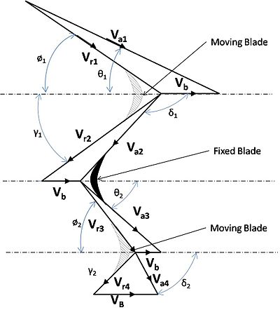
As shown in the above diagram there are two rings of moving blades separated by a ring of fixed blades. The velocity diagram in figure 2, shows the various components of steam velocity and the blade velocity of the moving blades.
where,
Va = absolute velocity of steam
Vr = relative velocity of steam
Vb = Blade velocity
θ = Nozzle angle
ø = Blade entrance angle
γ = Blade exit angle
δ = fluid exit angle
Form the above figure it can be seen that the steam, after exiting from the moving blades, enters into the fixed blades. The fixed blades redirect the steam into the next set of moving blades. Hence, steam losses its velocity in multiple stages than in a single stage.
Optimum Velocity
It is the velocity of the blades at which maximum power output can be achieved. Hence, the optimum blade velocity for this case is,
where n is the number of stages.
It is interesting to note that this value of optimum velocity is 1/n times that of the single stage turbine. This means that maximum power can be produced at much lower blade velocities.
However, the work produced in each stage is not the same. The ratio of work produced in a 2 stage turbine is 3:1 as one move from higher to lower pressure. This ratio is 5:3:1 in three stage turbine and changes to 7:5:3:1 in a four stage turbine.
Disadvantages of Velocity Compounding
- Due to the high steam velocity there are high friction losses
- Work produced in the low-pressure stages is very less.
- The designing and fabrication of blades which can withstand such high velocities is difficult.
Pressure compounding of Impulse Turbine

The pressure compounded Impulse turbine is also called as Rateau turbine, after its inventor. This is used to solve the problem of high blade velocity in the single-stage impulse turbine.
It consists of alternate rings of nozzles and turbine blades. The nozzles are fitted to the casing and the blades are keyed to the turbine shaft.
In this type of compounding the steam is expanded in a number of stages, instead of just one (nozzle) in the velocity compounding. It is done by the fixed blades which act as nozzles. The steam expands equally in all rows of fixed blade. The steam coming from the boiler is fed to the first set of fixed blades i.e. the nozzle ring. The steam is partially expanded in the nozzle ring. Hence, there is a partial decrease in pressure of the incoming steam. This leads to an increase in the velocity of the steam. Therefore the pressure decreases and velocity increases partially in the nozzle.
This is then passed over the set of moving blades. As the steam flows over the moving blades nearly all its velocity is absorbed. However, the pressure remains constant during this process. After this it is passed into the nozzle ring and is again partially expanded. Then it is fed into the next set of moving blades, and this process is repeated until the condenser pressure is reached.
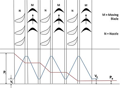
This process has been illustrated in figure 3.
where, the symbols have the same meaning as given above.
It is a three stage pressure compounded impulse turbine. Each stage consists of one ring of fixed blades, which act as nozzles, and one ring of moving blades. As shown in the figure pressure drop takes place in the nozzles and is distributed in many stages.
An important point to note here is that the inlet steam velocities to each stage of moving blades are essentially equal. It is because the velocity corresponds to the lowering of the pressure. Since, in a pressure compounded steam turbine only a part of the steam is expanded in each nozzle, the steam velocity is lower than of the previous case. It can be explained mathematically from the following formula i.e.
where,
V1 = absolute exit velocity of fluid
h1 = enthalpy of fluid at exit
V2 = absolute entry velocity of fluid
h2 = enthalpy of fluid at entry
One can see from the formula that only a fraction of the enthalpy is converted into velocity in the fixed blades. Hence, velocity is very less as compared to the previous case.
Velocity Diagram

The velocity diagram shown in figure 4 gives a detail about the various components of steam velocity and Blade velocity.
where, symbols have the same meaning as given above.
An important point to note from the above velocity diagram is that the fluid exit angle (δ) is 90⁰. This indicates that the whirl velocity of fluid at exit of all stages is zero, which is in compliance with the optimum velocity concept (as discussed earlier).
The ratio of work produced in different stages is similar to as discussed for the above type.
Disadvantages of Pressure Compounding
- The disadvantage is that since there is pressure drop in the nozzles, it has to be made air-tight.
- They are bigger and bulkier in size.
Pressure-Velocity compounded Impulse Turbine

It is a combination of the above two types of compounding. The total pressure drop of the steam is divided into a number of stages. Each stage consists of rings of fixed and moving blades. Each set of rings of moving blades is separated by a single ring of fixed blades. In each stage there is one ring of fixed blades and 3-4 rings of moving blades. Each stage acts as a velocity compounded impulse turbine.
The fixed blades act as nozzles. The steam coming from the boiler is passed to the first ring of fixed blades, where it gets partially expanded. The pressure partially decreases and the velocity rises correspondingly. The velocity is absorbed by the following rings of moving blades until it reaches the next ring of fixed blades and the whole process is repeated once again.
This process is shown diagrammatically in figure 5.
where, symbols have their usual meaning.
Pressure compounding of Reaction Turbine

As explained earlier a reaction turbine is one which there is pressure and velocity loss in the moving blades. The moving blades have a converging steam nozzle. Hence when the steam passes over the moving blades, it expands with decrease in steam pressure and increase in kinetic energy.
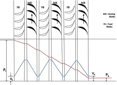
This type of turbine has a number of rings of moving blades attached to the rotor and an equal number of fixed blades attached to the casing. In this type of turbine the pressure drops take place in a number of stages.
The steam passes over a series of alternate fixed and moving blades. The fixed blades act as nozzles i.e. they change the direction of the steam and also expand it. Then steam is passed on the moving blades, which further expand the steam and also absorb its velocity.
This is explained in figure 6.
where, symbols have the same meaning as above.
Velocity Diagram

The velocity diagram given in figure 7 gives a detail about the various components of steam velocity and blade velocity.
where, symbols have the same meaning as above.
References
Further reading
- Venkanna B.K., Fundamentals of Turbomachinery, PHI Learning Private Limited, New Delhi, 2011.
- Yahya S. M., Turbines, Compressors and Fans (Fourth Edition), Tata Mcgraw Hill Educaition Private Limited, New Delhi, 2011.
- El-Wakil M. M., Powerplant Technology, Tata Mcgraw Hill Educaition Private Limited, New Delhi, 2010.
- M.S.GOVINDE GOWDA : MM PUBLISHERS DAVANGERE,KARNATAKA,INDIA