Profit margin: Difference between revisions
en>Velella m Reverted edits by 209.131.206.90 (talk) to last revision by ClueBot NG (HG) |
|||
| Line 1: | Line 1: | ||
'''Earth-Moon-Earth communication''', also known as '''moon bounce''', is a radio communications technique which relies on the propagation of radio waves from an [[Earth]]-based transmitter directed via reflection from the surface of the [[Moon]] back to an Earth-based receiver. | |||
== History == | |||
The use of the Moon as a passive communications satellite was proposed by [[John Bray (communications engineer)|W.J. Bray]] of the British [[General Post Office]] in 1940. It was calculated that with the available microwave transmission powers and low noise receivers, it would be possible to beam microwave signals up from Earth and reflect off the Moon. It was thought that at least one voice channel would be possible.<ref>{{cite book | |||
| last = Pether | |||
| first = John | |||
| title = The Post Office at War | |||
| publisher = [[Bletchley Park|Bletchley Park Trust]] | |||
| date = 1998 | |||
| page = 25 }}</ref> | |||
The "moon bounce" technique was developed by the [[United States Military]] in the years after [[World War II]], with the first successful reception of echoes off the Moon being carried out at [[Fort Monmouth, New Jersey]] on January 10, 1946 by [[John H. DeWitt]] as part of [[Project Diana]].<ref>{{cite book | |||
| last = Butrica | |||
| first = Andrew J. | |||
| title = To See the Unseen: A History of Planetary Radar Astronomy | |||
| publisher = NASA | |||
| date = 1996 | |||
| url = http://history.nasa.gov/SP-4218/ch1.htm | |||
|archiveurl=http://web.archive.org/web/20070823124845/http://history.nasa.gov/SP-4218/ch1.htm|archivedate=2007-08-23}}</ref> The [[Communication Moon Relay]] project that followed led to more practical uses, including a [[teletype]] link between the naval base at [[Pearl Harbor, Hawaii]] and [[United States Navy]] headquarters in [[Washington, DC]]. In the days before [[communications satellites]], a link free of the vagaries of [[Radio propagation#Sky-Wave Propagation|ionospheric propagation]] was revolutionary. | |||
Later, the technique was used by non-military commercial users, and the first amateur detection of signals from the Moon took place in 1953. | |||
== EME communications technical details == | |||
As the [[albedo]] of the Moon is very low (maximally 12% but usually closer to 7%), and the [[path loss]] over the [[1 E8 m|770,000 kilometre]] return distance is extreme (around 250 to 310 [[Decibel|dB]] depending on VHF-UHF band used, [[modulation]] format and [[Doppler shift]] effects), high power (more than 100 watts) and [[high-gain antenna]]s (more than 20 dB) must be used. | |||
In practice, this limits the use of this technique to the spectrum at [[VHF]] and above. | |||
The Moon must be above the horizon in order for EME communications to be possible. | |||
To determine ''EME Path Loss'' we need to know - | |||
# Moon distance from either the transmitting or receiving station | |||
# Transmitter station output in watts, expressed as [[Effective_radiated_power|ERP]] [roughly transmitter power output (minus feedline loss) x forward antenna gain] | |||
# Receive station gain (actual receiver gain minus feedline loss, x antenna gain) | |||
#The operating frequency of the transmitter and receiver | |||
Free space loss from an isotropic omnidirectional antenna is described by this formula. It calculates the surface area of an imaginary sphere of radius, d, that the radio wave illuminates uniformly: | |||
# Loss = <math>(\frac{4\pi d}{\lambda})^2</math> where pi ≈ 3.14, d = distance and lambda = wavelength, in meters | |||
# Lambda = c/F F = Hz, c = <math>3*10^8</math> meters/sec. | |||
# Lambda = <math>\frac{300}{F}</math> when F is in MHz. | |||
Substituting F into the free-space loss formula and converting to d into km: | |||
* Loss = <math>4*\pi *10^3 *F*\frac{d}{300}</math> '''or''' | |||
* Loss(dB) = <math>32.45 + 20\log{F} + 20\log{d}</math> | |||
Adding factors for reflection from the Moon results in | |||
* Loss-eme(dB) = 32.45 + 20Log(F) + 20Log(2*d) + 50.21 - 10Log(.065) | |||
The standard [[Radar#Radar_equation|radar path link formula]] is basis for EME path-loss calculations | |||
* <math>P_r = P_t*G_t*G_r*Loss</math> | |||
* Loss = <math>\rho*\lambda^2/(4*pi*)^3 *d^4</math> | |||
After including the factor for surface reflectivity it becomes | |||
* <math>Loss_{EME} \mathrm{(dB)} = 100.4 + 20 \log(F) + 40 \log(d) - 10 \log(\rho)</math> | |||
* <math>\rho = 0.065*\mathrm{D}^2 * \pi / 4</math> where <math>\mathrm{D}</math> is the Moon's diameter | |||
Since the diameter of the Moon is ≈ 3500 km | |||
* <math>\rho = 6.25 * 10^{11} m^2</math> | |||
The formula becomes | |||
* Loss-eme(dB) = 20Log(F) + 40LOG(d) - 17.49, F = MHz, d = km | |||
For some reason not specified, Josef has increased the loss by 3-dB producing: | |||
# Loss-eme(dB) = 103.4 + 20LOG(F) + 40LOG(d) - 10Log(rho) '''or''' | |||
# Loss-eme(dB) = 20Log(F) + 40LOG(d) - 14.49 | |||
Note that the distance from the Earth to the Moon varies because '''the orbit of the Moon is not perfectly circular''', it is somewhat elliptical with a mean radius of 240,000 miles. This means there is an apogee (the largest distance) and a perigee (the shortest distance). In addition, the orbital plane [[Precession|precesses]] with a principal period of [[Nutation#Of_the_Earth|18.6 years]]. | |||
Depending on the position of the Moon with respect to the Earth, Apogee can be as much as 406,700km, while Perigee can be as little as 356,400km. | |||
* This translates to as much as 2.25dB difference in path loss from apogee to perigee. | |||
* The mean distance from Earth to Moon is given as 384,400km. | |||
* These calculations consider the fact that the Moon is only 7% efficient as a reflector, use the [[Radar#Radar_equation|radar equation]] (which defines a two-way path-loss model) and the assumption that the Moon is a spherical reflector. | |||
== Current EME communications == | |||
[[Amateur radio]] (ham) operators utilize EME for two-way communications. EME presents significant challenges to amateur operators interested in working weak signal communications. Currently, EME provides the longest communications path any two stations on Earth can utilize for bi-directional communications. | |||
Amateur operations use VHF, UHF and microwave frequencies. All amateur frequency bands from 50 MHz to 47 GHz have been used successfully, but most EME communications are on the [[2-meter band|2 meter]], [[70-centimeter band|70-centimeter]], or [[23-centimeter band|23-centimeter]] bands. Common modulation modes utilized by amateurs are [[continuous wave]] with Morse Code, digital ([[JT65]]) and when the link budgets allow, voice. | |||
Recent advances in [[digital signal processing]] have allowed EME contacts, admittedly with low data rate, to take place with powers in the order of [[Orders of magnitude (power)|100 Watts]] and a single [[Yagi antenna]]. | |||
World Moon Bounce Day, June 29, 2009, was created by [[Echoes of Apollo]] and celebrated world wide as an event preceding the 40th anniversary of the [[Apollo 11]] Moon landing. A highlight of the celebrations was an interview via the Moon with [[Apollo 8]] astronaut [[Bill Anders]]. He was also part of the backup crew for Apollo 11. The University of Tasmania in Australia with their 26m dish was able to bounce a data signal off the surface of the Moon which was received by a large dish in the Netherlands - [[Dwingeloo Radio Observatory]]. The data signal was successfully resolved back to data setting a world record for the lowest power data signal returned from the Moon with a transmit power of 3 milliwatts - about 1,000th of the power of a strong flashlight filament globe. World Moon Bounce Day 2010 was set to precede the [[Apollo 13]] mission sometime in early 2010. The second World Moon Bounce Day was April 17, 2010 and coincided with the landing of Apollo 13 on its 40th anniversary. | |||
In October 2009 visual artist Daniela de Paulis and the CAMRAS radio amateurs association based at Dwingeloo radio telescope (NL) developed a new application of Moonbounce, called Visual Moonbounce, which allows moonbouncing images using the MMSSTV software. The technology was applied to a live performance called OPTICKS during which digital images are sent to the Moon and back in real time and projected live. | |||
== Modulation types and frequencies optimal for EME == | |||
VHF | |||
* [[Continuous Wave|CW]] | |||
* [[WSJT (Amateur radio software)|JT65A]] | |||
* [[WSJT (Amateur radio software)|JT65B]] | |||
[[UHF]] | |||
* [[Continuous Wave|CW]] | |||
* [[WSJT (Amateur radio software)|JT65C]] | |||
* [[Single-sideband modulation|SSB]] | |||
[[Microwave]] | |||
* [[Continuous Wave|CW]] | |||
* [[Single-sideband modulation|SSB]] | |||
== Other factors influencing EME communications == | |||
Doppler effect at 144MHz band - 300 Hz at Moonrise/set | |||
* At Moonrise, returned signals will be shifted approximately 300 Hz higher in frequency due to the Doppler effect between the Earth and Moon. | |||
* As the Moon traverses the sky to a point due south the Doppler effect approaches nothing. As the Moon sets, signals are shifted lower in frequency until at Moonset they are shifted 300 Hz lower. | |||
* Doppler effects cause many problems when tuning into and locking onto signals from the Moon. | |||
{{Listen | |||
|filename=Ssb-echo-3.ogg | |||
|title=EME SSB Transmission | |||
|description=A [[Single-sideband_modulation|single sideband]] contact between IZ1BPN in [[Italy]] and PI9CAM at the [[Dwingeloo Radio Observatory]]. IZ1BPN's transmission is shifted up in pitch slightly to compensate for PI9CAM's transmission being [[Doppler Shift|Doppler Shifted]] down. At the end of IZ1BPN's transmission you can hear the echo of his signal returning from [[the Moon]], again pitched down by Doppler Shift. | |||
|format=[[Ogg]]}} | |||
=== Gallery === | |||
<gallery> | |||
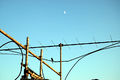
Image:EA6VQ_EME.jpg|An array of 8 Yagi antennas for 144 MHz EME at [http://www.vhfdx.net EA6VQ], Balearic Islands, Spain | |||
Image:144MHz_EME.jpg|A part of 144 MHz EME antenna array at WA6PY in California, USA | |||
Image:EME_dish.jpg|A dish antenna for microwave EME work at WA6PY, California, USA | |||
Image:I2FZX_UHF_EME_Antenna.png|A dish antenna for UHF EME at I2FZX, Milan, Italy | |||
File:SM3PWM EME Antenna.jpg|Amateur Radio antenna array used for Earth-Moon-Earth communication on 144 MHz. Location Kilafors in Middle Sweden. Owner Sverker Hedberg, SM3PWM. | |||
File:SM5BSZ EME Antenna.jpg|Amateur Radio antenna array used for Earth-Moon-Earth communication on 144 MHz. Location Jäder, Middle Sweden. Owner Leif Åsbrink, SM5BSZ. | |||
File:SM7BAE EME Antenna.jpg|Amateur Radio antenna array used for Earth-Moon-Earth communication on 144 MHz. Location Staffanstorp, South Sweden. Owner Kjell Rasmusson, SM7BAE. | |||
Image:Cheltenham_MD_USA_Navy_EME at [http://picasaweb.google.com/lh/photo/i8cEsvucoQAV8L18pORoQA?authkey=Gv1sRgCN3wm7eXt_ikTw&feat=directlink] | |||
</gallery> | |||
==References== | |||
<references/> | |||
http://www.opticks.info | |||
==See also== | |||
*[[Information theory]] | |||
*[[Lunar Laser Ranging experiment]] | |||
*[[Meteor burst communications]] | |||
*[[Passive repeater]] | |||
*[[Radar#Radar_equation|Radar Equation]] | |||
== External links == | |||
* [http://history.nasa.gov/SP-4217/ch2.htm NASA, ''Beyond the Ionosphere: the development of satellite communications''] | |||
* http://www.k5rmg.org/tech/EME.html (another calculator) | |||
* http://www.df9cy.de/tech-mat/pathloss.htm (gives formulas for EME path loss calculation) | |||
*[http://www.camras.nl] site of CAMRAS radio amateurs association at Dwingeloo radio telescope | |||
http://www.opticks.info | |||
*[http://echoesofapollo.com/moon-bounce/] World Moon Bounce Day - Echoes of Apollo | |||
*[http://www.wia.org.au/members/armag/2009/august/] Amateur Radio - August 2009 - Wireless Institute of Australia | |||
{{RF Propagation Navbox}} | |||
[[Category:Radio frequency propagation]] | |||
[[Category:Moon]] | |||
Revision as of 22:37, 28 January 2014
Earth-Moon-Earth communication, also known as moon bounce, is a radio communications technique which relies on the propagation of radio waves from an Earth-based transmitter directed via reflection from the surface of the Moon back to an Earth-based receiver.
History
The use of the Moon as a passive communications satellite was proposed by W.J. Bray of the British General Post Office in 1940. It was calculated that with the available microwave transmission powers and low noise receivers, it would be possible to beam microwave signals up from Earth and reflect off the Moon. It was thought that at least one voice channel would be possible.[1]
The "moon bounce" technique was developed by the United States Military in the years after World War II, with the first successful reception of echoes off the Moon being carried out at Fort Monmouth, New Jersey on January 10, 1946 by John H. DeWitt as part of Project Diana.[2] The Communication Moon Relay project that followed led to more practical uses, including a teletype link between the naval base at Pearl Harbor, Hawaii and United States Navy headquarters in Washington, DC. In the days before communications satellites, a link free of the vagaries of ionospheric propagation was revolutionary.
Later, the technique was used by non-military commercial users, and the first amateur detection of signals from the Moon took place in 1953.
EME communications technical details
As the albedo of the Moon is very low (maximally 12% but usually closer to 7%), and the path loss over the 770,000 kilometre return distance is extreme (around 250 to 310 dB depending on VHF-UHF band used, modulation format and Doppler shift effects), high power (more than 100 watts) and high-gain antennas (more than 20 dB) must be used.
In practice, this limits the use of this technique to the spectrum at VHF and above.
The Moon must be above the horizon in order for EME communications to be possible.
To determine EME Path Loss we need to know -
- Moon distance from either the transmitting or receiving station
- Transmitter station output in watts, expressed as ERP [roughly transmitter power output (minus feedline loss) x forward antenna gain]
- Receive station gain (actual receiver gain minus feedline loss, x antenna gain)
- The operating frequency of the transmitter and receiver
Free space loss from an isotropic omnidirectional antenna is described by this formula. It calculates the surface area of an imaginary sphere of radius, d, that the radio wave illuminates uniformly:
- Loss = where pi ≈ 3.14, d = distance and lambda = wavelength, in meters
- Lambda = c/F F = Hz, c = meters/sec.
- Lambda = when F is in MHz.


Substituting F into the free-space loss formula and converting to d into km:
- Loss = or
- Loss(dB) =


Adding factors for reflection from the Moon results in
- Loss-eme(dB) = 32.45 + 20Log(F) + 20Log(2*d) + 50.21 - 10Log(.065)
The standard radar path link formula is basis for EME path-loss calculations
- Loss =


After including the factor for surface reflectivity it becomes
- where is the Moon's diameter


Since the diameter of the Moon is ≈ 3500 km

The formula becomes
- Loss-eme(dB) = 20Log(F) + 40LOG(d) - 17.49, F = MHz, d = km
For some reason not specified, Josef has increased the loss by 3-dB producing:
- Loss-eme(dB) = 103.4 + 20LOG(F) + 40LOG(d) - 10Log(rho) or
- Loss-eme(dB) = 20Log(F) + 40LOG(d) - 14.49
Note that the distance from the Earth to the Moon varies because the orbit of the Moon is not perfectly circular, it is somewhat elliptical with a mean radius of 240,000 miles. This means there is an apogee (the largest distance) and a perigee (the shortest distance). In addition, the orbital plane precesses with a principal period of 18.6 years.
Depending on the position of the Moon with respect to the Earth, Apogee can be as much as 406,700km, while Perigee can be as little as 356,400km.
- This translates to as much as 2.25dB difference in path loss from apogee to perigee.
- The mean distance from Earth to Moon is given as 384,400km.
- These calculations consider the fact that the Moon is only 7% efficient as a reflector, use the radar equation (which defines a two-way path-loss model) and the assumption that the Moon is a spherical reflector.
Current EME communications
Amateur radio (ham) operators utilize EME for two-way communications. EME presents significant challenges to amateur operators interested in working weak signal communications. Currently, EME provides the longest communications path any two stations on Earth can utilize for bi-directional communications.
Amateur operations use VHF, UHF and microwave frequencies. All amateur frequency bands from 50 MHz to 47 GHz have been used successfully, but most EME communications are on the 2 meter, 70-centimeter, or 23-centimeter bands. Common modulation modes utilized by amateurs are continuous wave with Morse Code, digital (JT65) and when the link budgets allow, voice.
Recent advances in digital signal processing have allowed EME contacts, admittedly with low data rate, to take place with powers in the order of 100 Watts and a single Yagi antenna.
World Moon Bounce Day, June 29, 2009, was created by Echoes of Apollo and celebrated world wide as an event preceding the 40th anniversary of the Apollo 11 Moon landing. A highlight of the celebrations was an interview via the Moon with Apollo 8 astronaut Bill Anders. He was also part of the backup crew for Apollo 11. The University of Tasmania in Australia with their 26m dish was able to bounce a data signal off the surface of the Moon which was received by a large dish in the Netherlands - Dwingeloo Radio Observatory. The data signal was successfully resolved back to data setting a world record for the lowest power data signal returned from the Moon with a transmit power of 3 milliwatts - about 1,000th of the power of a strong flashlight filament globe. World Moon Bounce Day 2010 was set to precede the Apollo 13 mission sometime in early 2010. The second World Moon Bounce Day was April 17, 2010 and coincided with the landing of Apollo 13 on its 40th anniversary.
In October 2009 visual artist Daniela de Paulis and the CAMRAS radio amateurs association based at Dwingeloo radio telescope (NL) developed a new application of Moonbounce, called Visual Moonbounce, which allows moonbouncing images using the MMSSTV software. The technology was applied to a live performance called OPTICKS during which digital images are sent to the Moon and back in real time and projected live.
Modulation types and frequencies optimal for EME
VHF
Other factors influencing EME communications
Doppler effect at 144MHz band - 300 Hz at Moonrise/set
- At Moonrise, returned signals will be shifted approximately 300 Hz higher in frequency due to the Doppler effect between the Earth and Moon.
- As the Moon traverses the sky to a point due south the Doppler effect approaches nothing. As the Moon sets, signals are shifted lower in frequency until at Moonset they are shifted 300 Hz lower.
- Doppler effects cause many problems when tuning into and locking onto signals from the Moon.
My name is Darrel Skirving but everybody calls me Darrel. I'm from Great Britain. I'm studying at the university (2nd year) and I play the Lute for 9 years. Usually I choose music from the famous films :D.
I have two sister. I love Motor sports, watching TV (The Simpsons) and Fencing.
Look at my blog; Hostgator 1 Cent Coupon
Gallery
-
 An array of 8 Yagi antennas for 144 MHz EME at EA6VQ, Balearic Islands, Spain
 -
 A part of 144 MHz EME antenna array at WA6PY in California, USA
 -
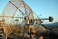 A dish antenna for microwave EME work at WA6PY, California, USA
 -
 A dish antenna for UHF EME at I2FZX, Milan, Italy
 -
 Amateur Radio antenna array used for Earth-Moon-Earth communication on 144 MHz. Location Kilafors in Middle Sweden. Owner Sverker Hedberg, SM3PWM.
 -
 Amateur Radio antenna array used for Earth-Moon-Earth communication on 144 MHz. Location Jäder, Middle Sweden. Owner Leif Åsbrink, SM5BSZ.
 -
 Amateur Radio antenna array used for Earth-Moon-Earth communication on 144 MHz. Location Staffanstorp, South Sweden. Owner Kjell Rasmusson, SM7BAE.


References
- ↑ 20 year-old Real Estate Agent Rusty from Saint-Paul, has hobbies and interests which includes monopoly, property developers in singapore and poker. Will soon undertake a contiki trip that may include going to the Lower Valley of the Omo.
My blog: http://www.primaboinca.com/view_profile.php?userid=5889534 - ↑ 20 year-old Real Estate Agent Rusty from Saint-Paul, has hobbies and interests which includes monopoly, property developers in singapore and poker. Will soon undertake a contiki trip that may include going to the Lower Valley of the Omo.
My blog: http://www.primaboinca.com/view_profile.php?userid=5889534
See also
- Information theory
- Lunar Laser Ranging experiment
- Meteor burst communications
- Passive repeater
- Radar Equation
External links
- NASA, Beyond the Ionosphere: the development of satellite communications
- http://www.k5rmg.org/tech/EME.html (another calculator)
- http://www.df9cy.de/tech-mat/pathloss.htm (gives formulas for EME path loss calculation)
- [1] site of CAMRAS radio amateurs association at Dwingeloo radio telescope